Why a Comparison Table Outperforms a Datasheet Stack
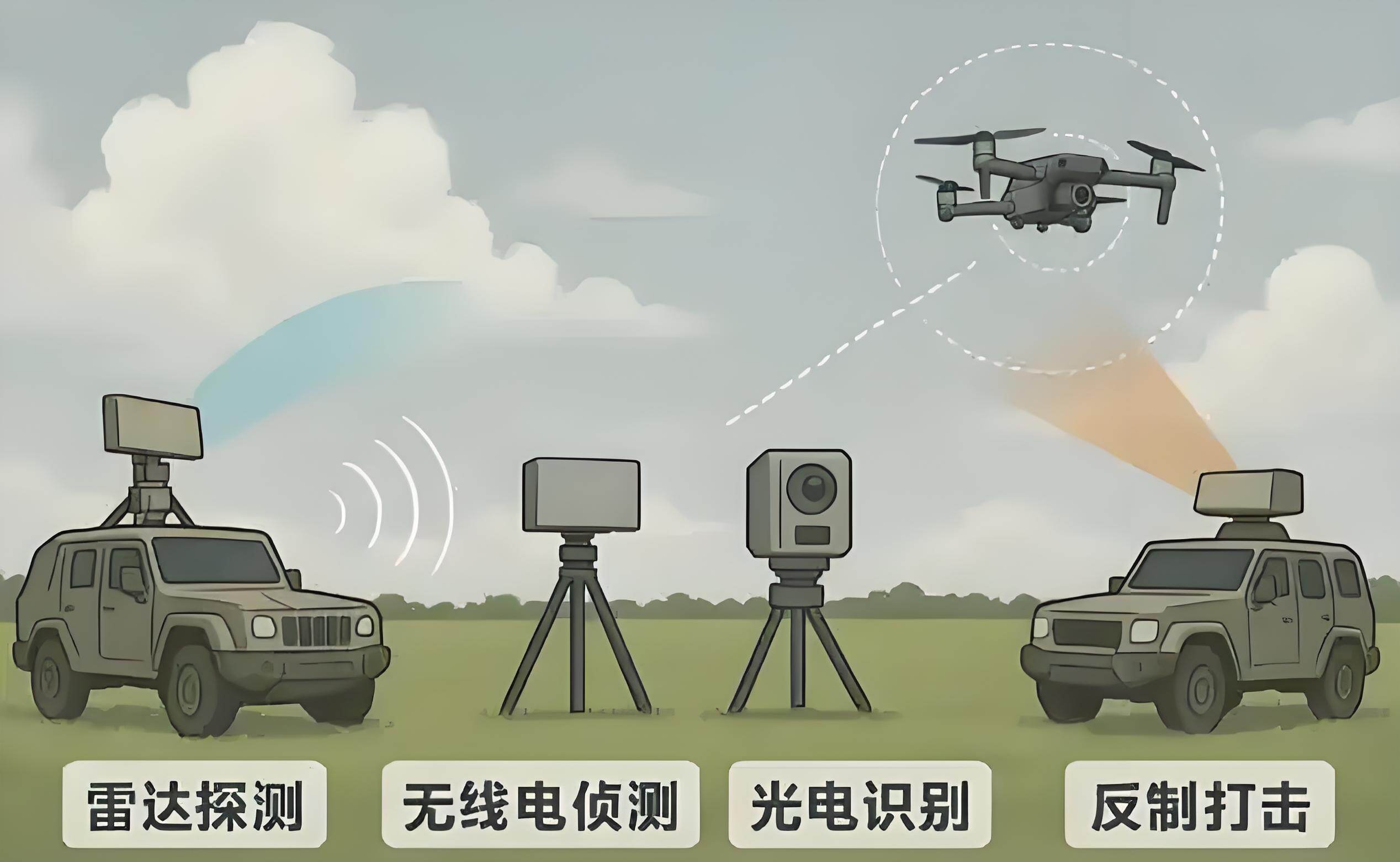
Drone countermeasure systems typically operate across five to eight frequency bands and three or four power levels. Errors often arise when comparing data across multiple documents: a 50 W module in one band is not equivalent to a 50 W module in another, and a 100 W amplifier on a 34-degree panel does not perform like a 100 W amplifier on an omni-directional antenna.
This page displays numbers side by side. Use it as a starting grid, then verify against measured data for the specific model. For details on each selection, read thedrone jammer module selection guide.
Drone Link Band Reference
The table below outlines the typical use case for each band, required module capabilities, and key antenna-side considerations. Frequencies are listed as ranges because real-world links hop frequencies and modules support usable bandwidth.
| Band | Common drone applications | Module Requirements | Antenna note |
|---|---|---|---|
| 433 MHz | Long-range remote control with legacy telemetry | Narrowband, high-efficiency, and tolerant of high VSWR | Large components; maintain clearance from metal structures |
| 868 / 915 MHz | Telemetry, Remote ID, and control links | Region-specific range; 20 MHz of usable bandwidth is sufficient | Vertical polarization matches most links |
| 1.2 GHz | GNSS L2 / L5: Video Links | Support both 1.227 GHz and 1.176 GHz if GNSS is the target. | Separate the antenna from the L1 unit to prevent coupling. |
| 1.4 GHz | Video downlink; licence-exempt links in certain regions | Wideband, flat gain across the band | Panel antennas perform well in approach corridors. |
| 1.5 GHz | GNSS L1 at 1.575 GHz | Narrowband with steep filtering to protect adjacent services | Point to the sky-facing hemisphere, not the horizon. |
| 2.4 GHz | Control and video: the most common consumer connections | 80 to 100 MHz usable bandwidth with excellent gain flatness | 18 dBi panels provide approximately 30 to 40 degrees of beamwidth. |
| 5.8 GHz | FPV video, high-bandwidth links | 200 MHz or higher, low-loss connectors | Severe cable loss here; keep runs under 3 meters. |
Two key takeaways from the table: First, at least two modules are required to completely deny a GNSS position fix, not just degrade it. Second, the two consumer bands—2.4 GHz and 5.8 GHz—handle most of the practical load. This is why they dominate module availability and why their antenna systems warrant the most attention.
Power Tiers and What They Actually Get You
Power tiers in this industry are typically standardized at 10, 20, 30, 50, and 100 W continuous. The table outlines what each tier generally means for integration.
| Tier | Typical use | Supply | Thermal management | Typical deployment |
|---|---|---|---|---|
| 10 W | Short-range modules, indoor rooms, handheld builds | 12 to 28 V, 1 to 2 A | Small heatsink; passive cooling is usually sufficient. | Single room, vehicle cabin, portable unit |
| 20 W | Room-scale coverage with a directional antenna | 24 to 28 V, approximately 3 A | Aluminum flange with airflow | Meeting room, small hall, checkpoint |
| 30 W | General-purpose building block for multi-band arrays | 24 to 28 V, 3.5 to 4 A | Forced-air or machined heatsink wall | Corridor, gate, mid-size perimeter sector |
| 50 W | Higher-intensity sectors, longer approach paths | 28 V, 6 to 8 A | Active cooling recommended | Perimeter sector, vehicle roof mount |
| 100 W | Long-range or high-clutter environments | 28 to 48 V, 12 A and above | Liquid or high-flow forced air | Fixed installation with mast-mounted head |
How to read the power column
The key figure is continuous output at the antenna connector, measured at the actual case temperature you'll encounter and into the real antenna you'll use. Three corrections almost always apply.
- Connector vs. RadiatedAccount for cable and connector loss. At 5.8 GHz, a 5-meter run can consume half your power.
- Duty cycle.Peak rating is not a continuous rating. Request the derating curve for your ambient temperature.
- Flatness.A module specified at 50 W may deliver 50 W at the band center and 30 W at the edges. If the threat hops, the edges matter.
Combine Bands Without Losing Power
There are two ways to build a multi-band head, each with different trade-offs.
Modular design with dedicated antennas
Each band uses its own amplifier and antenna. This ensures strong isolation, independent failure handling, and separate aiming per band. The trade-off is mechanical: more mounting points, cables, and weight.
Combine modules
Multiple amplifiers feed a single broadband antenna via a combiner. This approach yields a compact build and reduces the number of antennas required. However, every combiner introduces insertion loss—typically 0.5 to 1.5 dB per path—and ports require isolation to prevent one module from feeding back into another. Beyond three bands, the loss and isolation budget typically become the limiting factor rather than the amplifiers themselves.
Multi-band modules
A single module covering multiple bands is the simplest to integrate and certify as one unit. Per-band efficiency is typically lower than with dedicated narrowband designs, and a fault disables all bands simultaneously. For portable units where weight and wiring are critical, this approach usually offers the best trade-off. For fixed installations where each sector faces different threat profiles, separate modules provide greater flexibility.
Venue Selection Matrix
| Venue | Top Bands to Cover First | Power tier | Antenna approach |
|---|---|---|---|
| Single meeting room | 2.4 GHz, 5.8 GHz, GNSS L1 | 10 to 20 W per band | One ceiling omnidirectional light or two small panels |
| Corridor or single entrance | 2.4 GHz, 5.8 GHz | 30 W per band | Narrow panel along the approach axis |
| Facility Perimeter | 2.4 GHz, 5.8 GHz, GNSS L1/L2, control band | 50 to 100 W per sector | Three or four sectors with overlapping coverage |
| Vehicle-mounted | 2.4 GHz, 5.8 GHz, GNSS, 433 or 900 MHz | 30 to 50 W per band | Roof-mounted mast, vertical polarization, short cables |
| Portable backpack unit | Multi-band module set | 10 to 30 W per band | Integrated panel array, operator-targeted |
What the Table Can't Tell You
Two factors fall outside any specification grid. First, the environment: metal shelving, reinforced concrete, and glass partitions can alter signal propagation by tens of dB. Second, the victim receiver: a modern frequency-hopping link with forward error correction behaves very differently from an analog video transmitter; the same EIRP that disrupts one link may only degrade another.
That is why the honest specification process is: select the band set from the threat, choose the power tier from the volume, order one sample, measure it in the real environment, and adjust. A supplier who refuses to provide measured data or a sample for evaluation is asking you to accept the risk of the entire project.
Compliance and Operating Envelope
Modules are components, not finished products. Transmission authorization, applicable power limits, and permitted bands depend on the country of use; the integrator bears full responsibility for the final device. In most jurisdictions, interference with public mobile networks, aviation navigation, emergency services, or life-safety systems is prohibited regardless of output power. Before deployment, document the intended bands and power levels in writing with the end user, and verify the local regulatory status for each band using the matrix above.
Next Steps
Once a configuration is selected, validate it using the measurements intesting and acceptance checklist.
If you have a venue and a threat set, the fastest path is a brief specification discussion: send us the frequency bands, protected volume, and mounting constraints. We'll respond with a module and antenna combination, along with measured performance data for those models. Current hardware options are listed in thedrone jammer module range, and the rationale for each band and antenna selection is detailed in theselection guide.