Start from the Threat, Not the Catalog
Most integration projects fail the same way: someone opens a module catalogue, picks the highest power rating, and works backward to the antenna and enclosure. The result is usually wrong frequency coverage, overheating in a sealed housing, or interference with adjacent bands it was never designed for.
A drone jammer module is a component of a system. Its function is to deliver sufficient energy into the specific channels used by the threat and within the protected volume, without spilling outside. Every selection decision stems from this requirement.
This guide covers the four decisions that determine whether a build works: which bands, how much power, which antenna, and how the module is integrated. For side-by-side raw numbers, see the companion article.drone jammer band and power comparison tableDisplays typical coverage, power tiers, and module options in a single grid.
Step 1: Map the Channels You Need to Cover
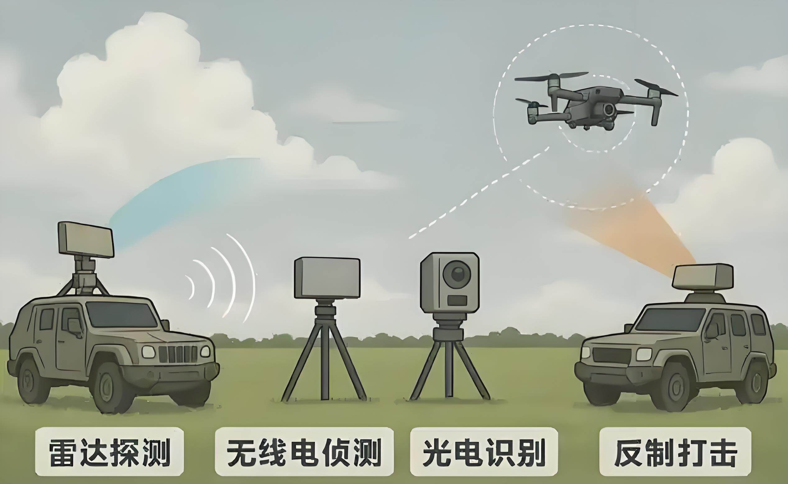
Drone links do not operate on a single frequency. A typical multirotor carries at least two radios, often three: one for command and control, one for video downlink, and a GNSS receiver. Operating bands vary by airframe, radio firmware, and region.
What each link typically looks like
- Command and control:typically 2.4 GHz or 900 MHz, with 433 MHz still found on older or long-range equipment. Frequency hopping means the entire band matters, not just a single channel.
- Video downlink:Most FPV systems operate in the 5.8 GHz band, with some 2.4 GHz and 1.2 GHz analog gear still in use. Wideband video requires wideband coverage.
- GNSS:1.575 GHz for L1, 1.227 GHz for L2/L5.. Covering only L1 leaves a receiver that can still maintain a position fix on other constellations.
- Telemetry and remote ID:868 MHz in Europe, 915 MHz in North America, with 2.4 GHz modules on some platforms.
The practical rule is to define the threat set first, then select one module per band group instead of using a single wideband module that operates at low efficiency. While wideband amplifiers simplify integration, their gain flatness across a 2 GHz span typically degrades compared to a narrowband module designed for a single band.
Bandwidth, not just center frequency
A module rated at 2.4 GHz with 100 MHz of usable bandwidth will comfortably cover the ISM band. The same module cannot support a hopping link that extends down to 2.3 GHz. Request the specified frequency range with gain measured at both edges, not just at the center. A datasheet listing only a single frequency and power figure provides little insight into how the module performs at the band edges.
Step 2: Match Power to Volume
Output power is the metric everyone wants to know—and most often misunderstands. What actually reaches the target iseffective isotropic radiated power: module output plus antenna gain minus cable and connector loss. A 30 W module feeding an 18 dBi panel through 2 dB of cable is a very different system from a 50 W module on a 6 dBi omni antenna.
Estimated cost
For a rectangular room, start by calculating the EIRP needed to maintain a jamming-to-signal ratio above the receiver's tolerance at the far wall, then add margin for multipath and body absorption. Indoor spaces with metal furniture and glass partitions typically require 6 to 10 dB more than free-space calculations suggest. Outdoor open areas are easier to predict but cover a much larger volume; this is why fixed outdoor installations usually combine several lower-power heads instead of using a single high-power unit.
Be skeptical of any published distance figure, including ours. Range depends on the receiver's sensitivity, drone altitude, antenna orientation, and local clutter. A module rated for "1 to 3 km" may achieve that in one direction but fail at 400 m in another. To be accurate, always specify test conditions: receiver model, antenna type, height, and measurement method.
Duty cycle and thermal headroom
Jamming is a continuous-duty application. A module rated at 50 W peak into a matched load with a 10% duty cycle does not qualify as a 50 W continuous module. Verify the continuous power rating, the specified case temperature, and the derating curve. Inside a sealed IP65 enclosure, assume you have only about half the thermal capacity suggested in the datasheet unless you have measured it yourself.
Two practical steps make a real difference: mount the amplifier flange directly to a heatsink using a thermal pad (not just thermal paste), and place the temperature sensor on the flange, not the PCB. If the flange remains too hot to touch for five seconds during full-power operation, the design requires more airflow or a larger heatsink.
Step 3: Select the Antenna to Shape Coverage
The antenna determines where the signal goes. A panel antenna with 15 to 18 dBi gain focuses the beam within approximately 30 to 40 degrees—ideal for corridors, entryways, or single approach paths. An omnidirectional antenna with 3 to 6 dBi covers a wider area at lower intensity, making it suitable for rooms or small yards.
Match gain to geometry
For perimeter deployments, three to four 60–90-degree sector antennas typically outperform a single omnidirectional antenna. Each sector can be aimed at actual approach paths while maintaining lower total radiated power for equivalent coverage. For indoor rooms, a centrally mounted ceiling-level omnidirectional antenna is usually the simplest solution, avoiding the dead zones that directional antennas create behind them.
Polarization matters as much as gain. Most drone links use vertical polarization, so a vertically mounted panel aligns directly with them. Cross-polarized reception can incur 15 to 20 dB loss—no amount of extra amplifier power can compensate for this.
Practical antenna notes
- Use the connector specified by the module. An N-to-SMA adapter introduces signal loss and creates a mechanical weak point at the most critical location.
- Keep cable runs short. At 5.8 GHz, 5 meters of RG58 incurs roughly 3 dB loss—half your output power is lost before reaching the antenna.
- Check VSWR after installation, not just on the bench. A damaged cable or a water-filled connector will cause rising VSWR and an overheated amplifier.
Step 4: Integrate to Preserve the Numbers
A module that passes bench tests may still fail in the field. Four integration issues account for most failures.
Power supply
Amplifiers draw current in bursts when the envelope changes. Size the power supply for at least 1.3 times the nominal current and use short, thick leads. Voltage sag during a hop sequence causes spectral splatter that spills outside the intended band.
Filter and isolate
Multi-band systems create energy coupling between adjacent modules. Use cavity filters or circulators when bands are close, and space antennas by at least a quarter wavelength at the lowest operating frequency. Without isolation, harmonics from one module can interfere with another, causing the combined system to fail emissions compliance.
Control and monitoring
For anything beyond a bench prototype, expose enable lines, forward and reverse power telemetry, and temperature readings. Proving that a unit operated at 42 degrees and 1.2:1 VSWR during a complaint is worth more than any datasheet claim.
Housing
Enclose the unit, but ensure heat can escape. Where possible, use a machined heatsink as part of the housing wall and route the antenna connector through a bulkhead fitting instead of a cable gland.
Questions to Ask a Supplier Before Committing
The answers distinguish a component vendor from a partner.
- Can you provide the measured output power and gain flatness across the full specified band using the described test setup?
- What is the continuous rating at the actual case temperature we will see, and what is the derating curve?
- Can the band plan be adjusted? For example, can a 5.8 GHz module be shifted to cover 5.15–5.35 GHz for a specific deployment?
- Built-in protections include over-temperature, over-current, reverse polarity, and VSWR foldback.
- What is the sample lead time, MOQ, and what documentation ships with each unit?
For compliance, clarify responsibilities: modules are components. The final device, its enclosure, labeling, and operational authorization are the integrator's responsibility and must comply with the regulations of the country of use. CE and FCC marks on a finished product do not apply to bare modules. In most jurisdictions, transmitting equipment that interferes with public mobile networks, aviation, or emergency services is prohibited regardless of power level; therefore, define the operating envelope with the end user in writing before deployment.
Five Common Mistakes
- Buying power instead of coverage.Doubling amplifier power adds 3 dB. Switching from a 34-degree panel to a 60-degree sector can provide significantly more usable coverage.
- Ignoring the GNSS band split.Covering L1 leaves only L2 and L5 receivers operational.
- Testing indoors using a dummy load.A load test confirms the module functions, not the antenna system.
- One module per band is sufficient.Two antennas on the same band pointing in opposite directions require isolation, not just a splitter.
- Never recording the baseline.Without a pre-installation spectrum sweep, you cannot distinguish your own harmonics from environmental interference.
What's Next
Before handover, run the configuration through bench and field checks at ourtesting and acceptance checklist.
If you already know your threat bands and have a rough geometry, the next step is a band and power comparison rather than another brochure: see theband and power reference tablefor typical module options at each frequency. If you would rather start from our current hardware, thedrone jammer module rangeLists modules by band with continuous power, supply voltage, and connector type.
For a specific deployment, provide the target bands, protected volume, and mounting constraints. We will respond with a recommended module and antenna combination, along with measured data for that model instead of generic claims.